- Your cart is empty
- Continue Shopping


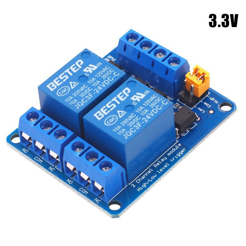
SPECIFICATION:
It has a 1×4 (2.54mm pitch) pin header for connecting power (5V and 0V), and for controlling the 2 relays. The pins are marked on the PCB:
Advanced:
The pins of the 1×3 pin header are marked on the PCB:
If opto isolation is required, an isolated 5V supply should be used. For normal operation, a jumper between pins 1 and 2 selects the 5V signal from the 1×4 pin header. This means both the “input side”, and “relay side” use the same 5V supply, and there is no opto-isolation.


Reviews
There are no reviews yet.